
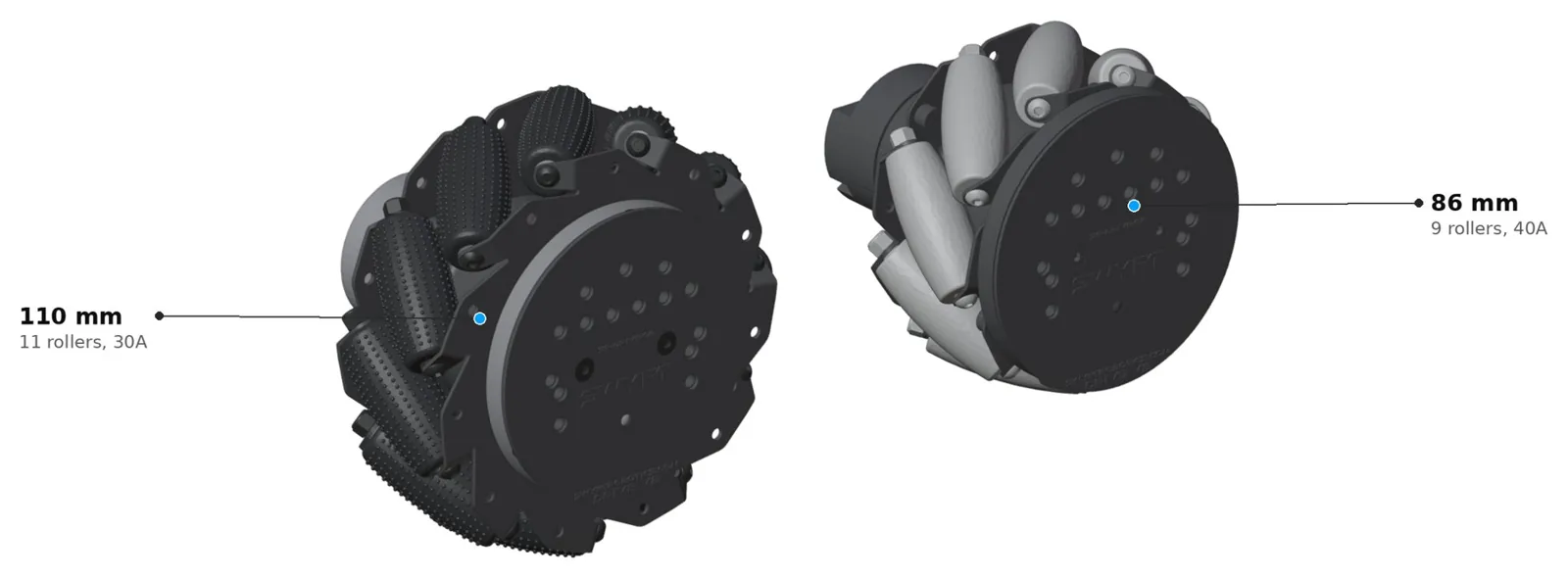
This guide covers building one SWYFT Drive V2 module and mounting it with the V2 Frame Kit. Build all four modules the same way. The pictures show the 110 mm module. The 86 mm module goes together the same way, with the differences called out below. Each module takes about 30 minutes to build.
| 110 mm | 86 mm | |
|---|---|---|
| Module pack SKU | SR-DRIVE-110mm-02 |
SR-DRIVE-02 |
| Frame kit SKU | SR-DRIVE-FRAME-110mm-02 |
SR-DRIVE-FRAME-02 |
| Rollers per wheel | 11 (30A, traction spikes) | 9 (40A) |
| Module weight | 640 g | 575 g |
| Gear ratio | 12.7:1 | 12.7:1 |
| Item | Notes |
|---|---|
| 2 mm Allen key | Included. For the M3 button-head and M3 countersunk screws. |
| 2.5 mm Allen key | Included. For the M4 button-head screws and the M3 socket-head back-plate screws (Frame Kit). |
| 5.5 mm wrench | Holds the M3 roller lock nuts in step 14. |
| Blue Loctite | Included. Use it on every screw except the roller screws, which use lock nuts. |
| Grease | Generic grease, 2 tubes included |
Allen key tip: put the long end in the screw and turn the short end with your fingers. You get plenty of force this way without stripping the small screws.
Loctite tip: squeeze a small drop onto a scrap of the parts bag and dip just the screw threads into it. You need very little.
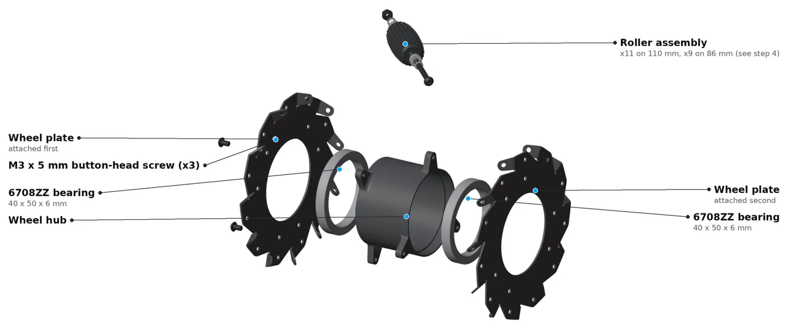
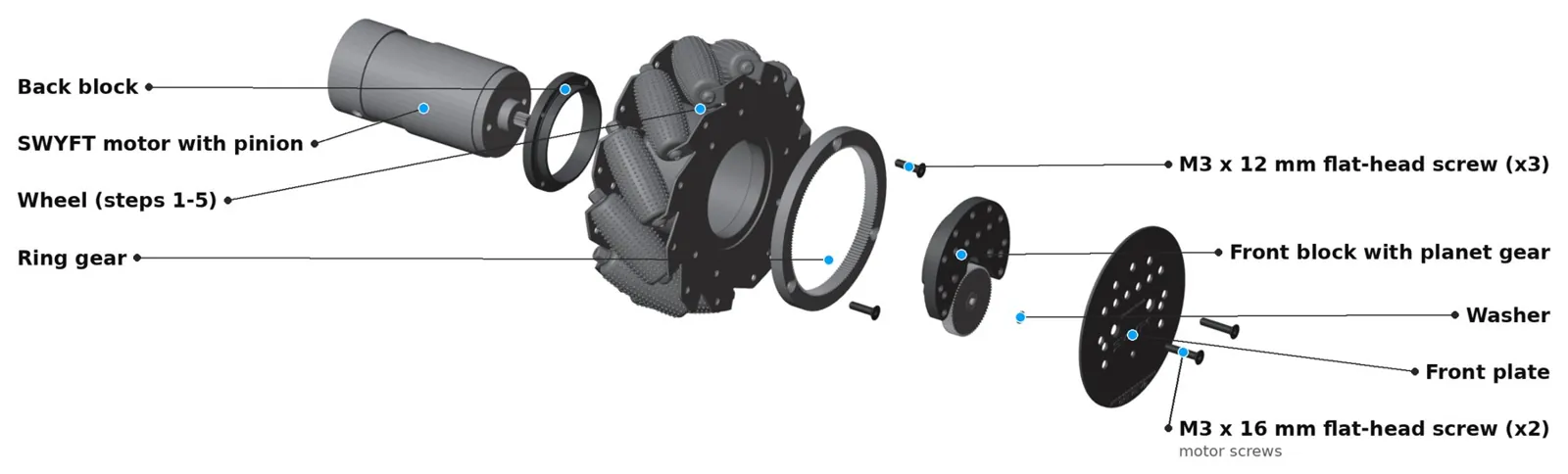
In the step pictures, blue = parts you add in that step, grey = parts already in place, and the orange arrow shows which way a part moves.
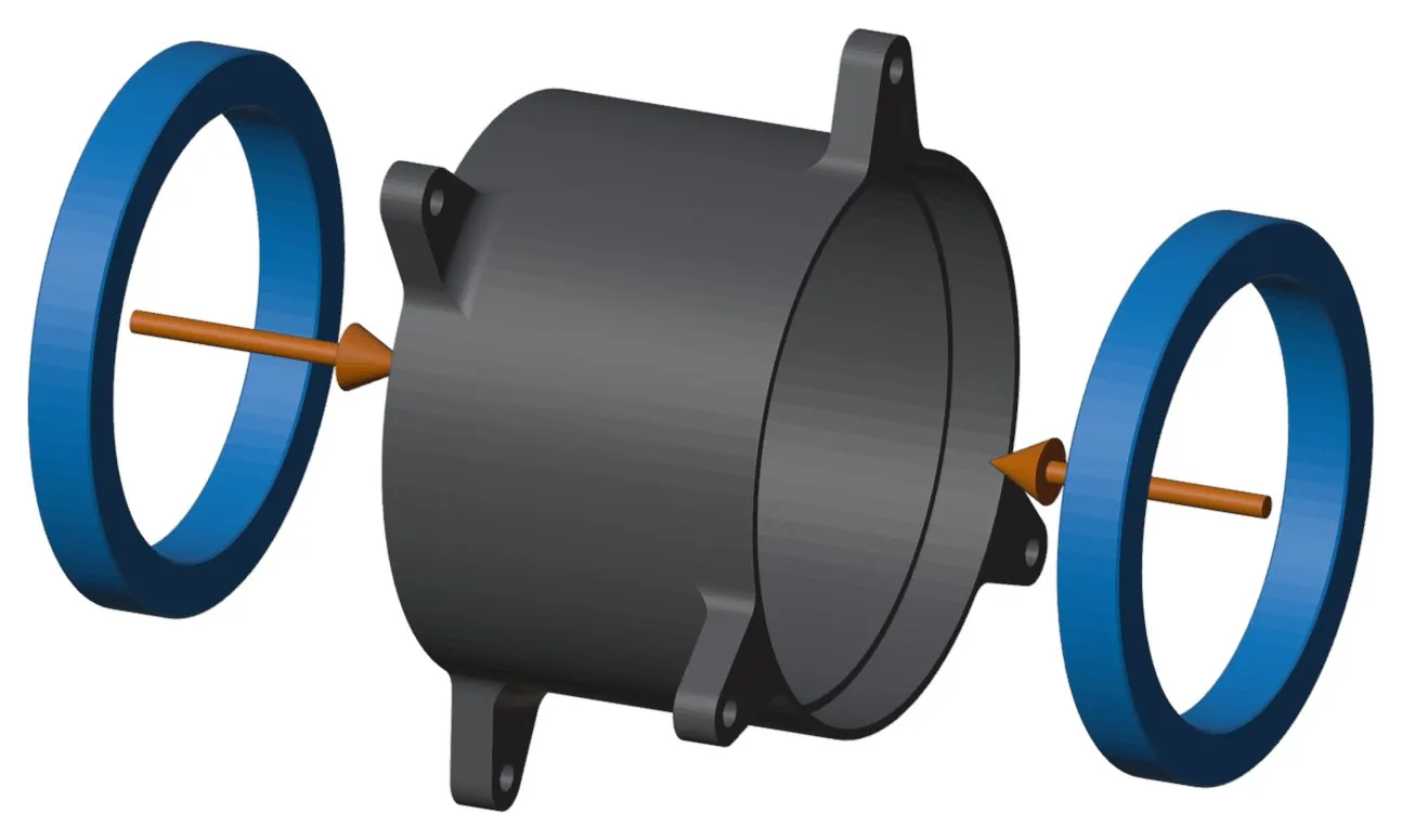
Take the two large 6708ZZ bearings out of the bearing bag and set the bag aside. Press one bearing into each side of the wheel hub by hand until it sits flush with the hub face. Some take firm pressure.
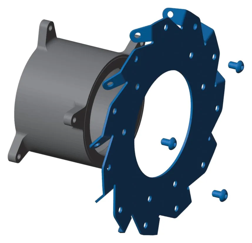
Set one wheel plate on the hub. Either side of the hub works. Add Loctite and install the 3 M3 × 5 mm button-head screws through the plate into the hub. Snug all three most of the way first, then tighten them.
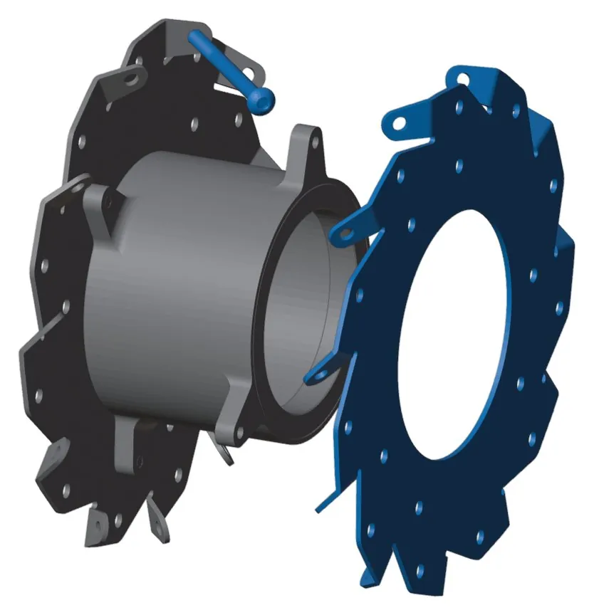
Set the second wheel plate on the other side of the hub. Don't screw it down yet.
110 mm: the plate can sit in six positions, and only one of them lines up with the roller holes in the first plate. Push a long M3 × 45 mm roller screw through the first plate, then turn the second plate until the screw passes straight through a hole. In the wrong positions the gap for the roller ends up too short or too long. Check this before you add rollers, because it is easy to be one position off.
86 mm: set the plate on top and line up the holes.
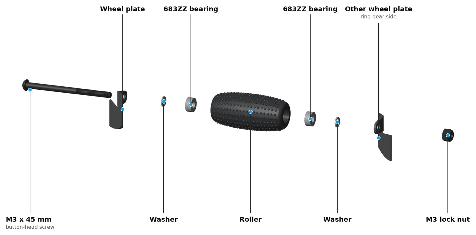
Press a small bearing into each end of the roller.
The M3 × 45 mm screw goes through the wheel plate first, then: washer → 683ZZ bearing → roller → 683ZZ bearing → washer → the other wheel plate → M3 lock nut.
The screw heads can go on either side, but put the lock nuts on the ring gear side (the second wheel plate, where the ring gear goes in step 6).
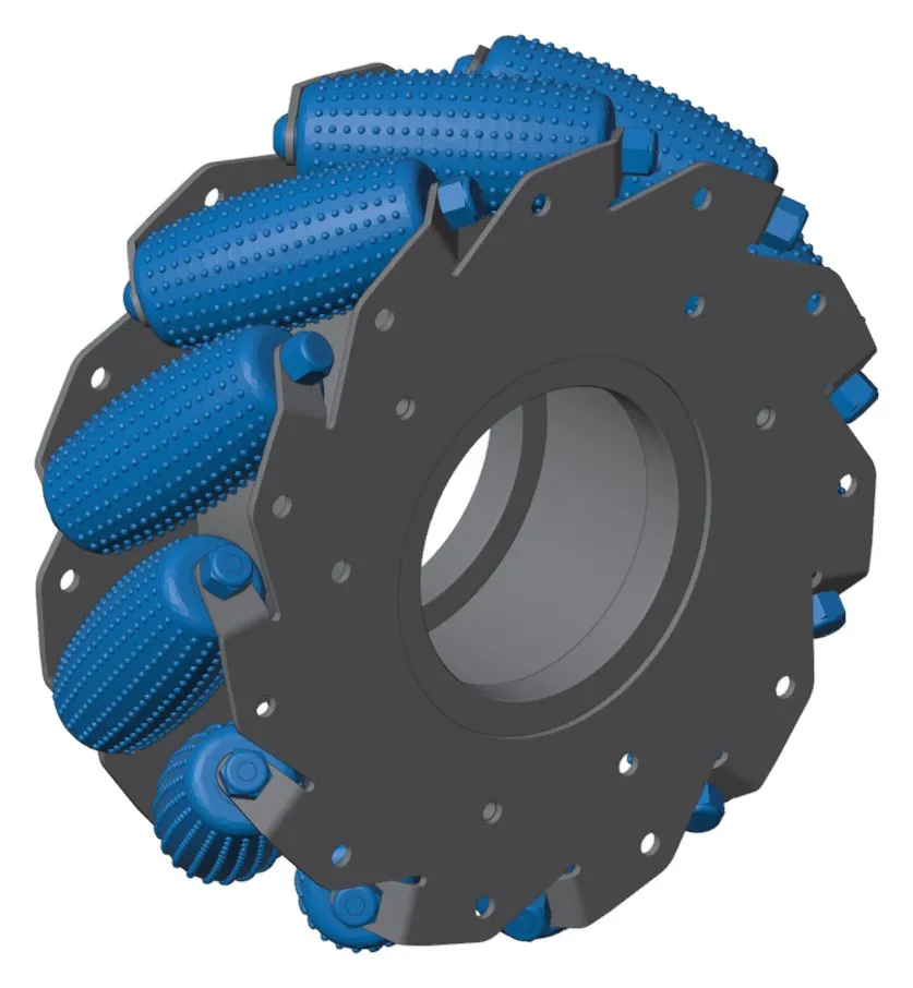
Repeat for every roller: 11 on a 110 mm wheel, 9 on an 86 mm wheel.
The last few are tighter. Push the screw only partway in, slide on the washer, roller, and bearings, then push the screw through into the second plate and add the nut. Extra washers are included in case you lose some.
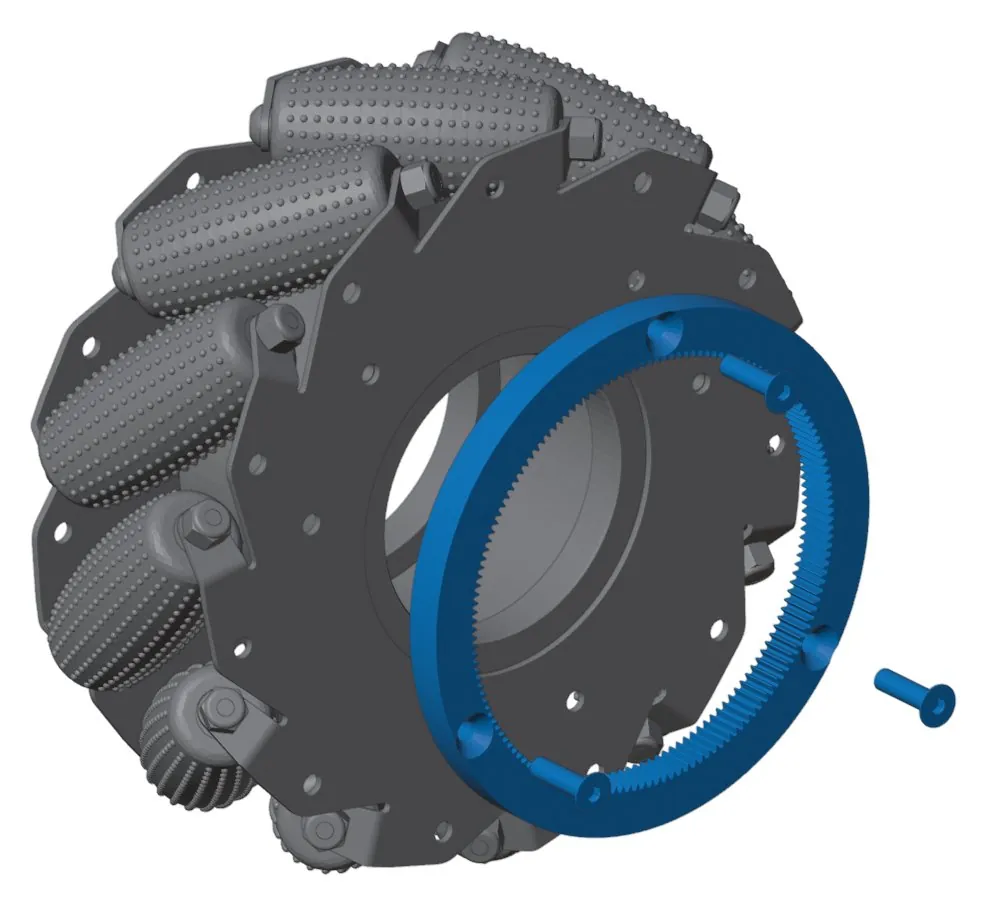
Find the shorter of the two flat-head screw sizes: 3 M3 × 12 mm. Add Loctite. Put each one through the ring gear and the second wheel plate, into the hub. Use the holes that have hub threads behind them. Start all three before tightening any of them. They can take a little extra push to get through the ring gear.
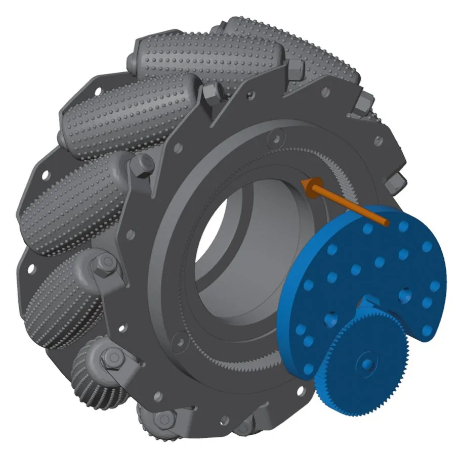
The planet gear comes installed on the front block. Set the block into the bearing inside the ring gear and press it in evenly with two thumbs until it snaps into place and sits flat. No hammer is needed.
Turn the wheel to check it. If the block sticks up on one side when you look from the side, press it in more. If it went in crooked, push it back out from the other side and try again.
If you feel resistance, slightly loosen the three screws holding the ring gear, spin it by hand, then retighten the three screws. A little resistance is normal and goes away after running the module for about 30 seconds.
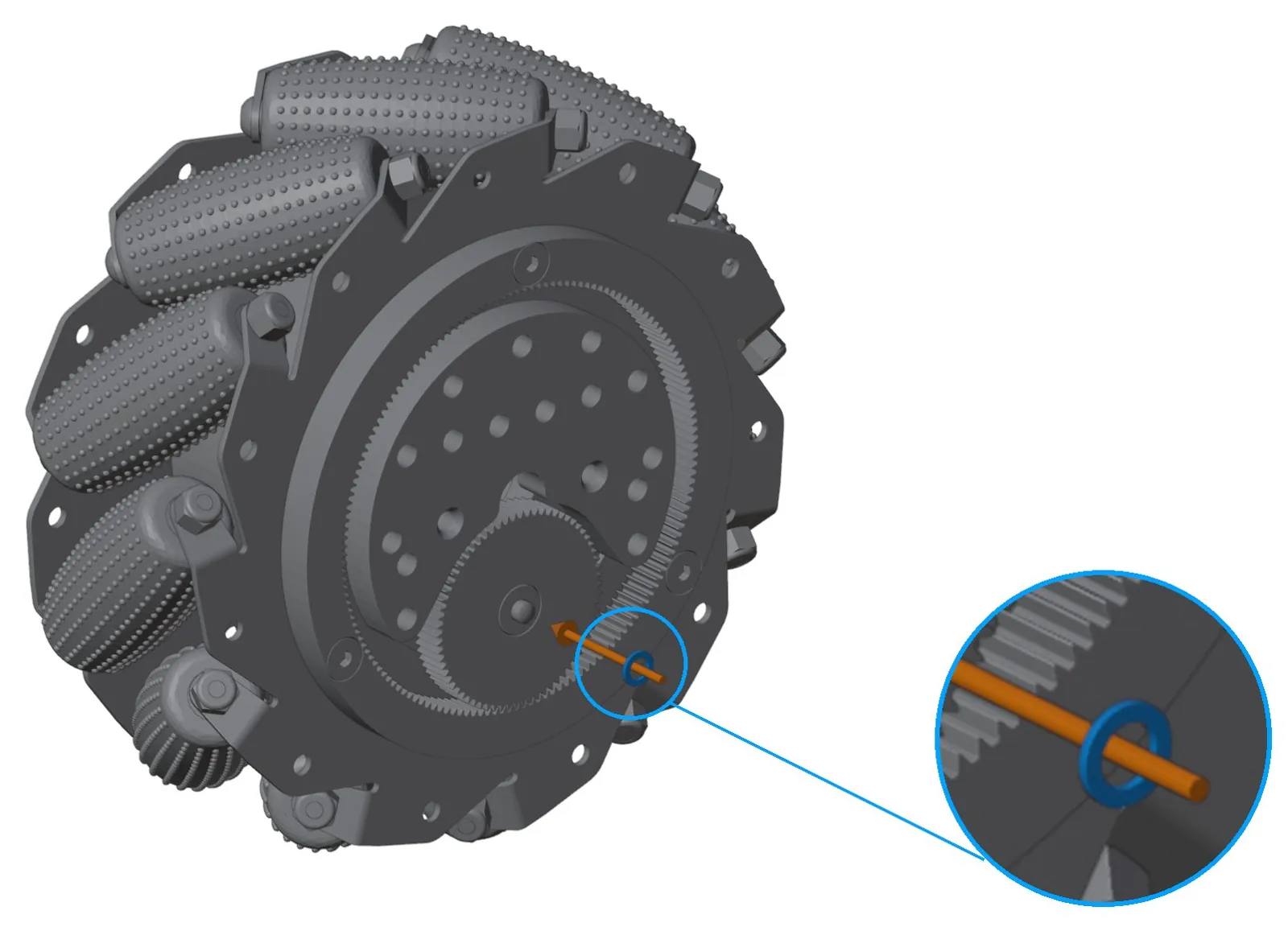
Put one small washer on the planet gear's bearing. It keeps the front plate from rubbing the bearing.
Cut the tip off one grease tube and run a bead of grease all the way around the ring gear teeth. That's all it needs.
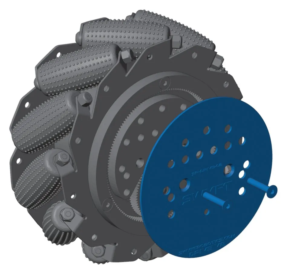
Set the front plate on so that the hole just below the SWYFT logo goes over the planet gear's pin. Add Loctite to the 2 longer M3 × 16 mm flat-head screws and drop them into the countersunk holes above the "S" and "T" of the logo. These are the motor screws. Don't tighten them yet. Hold them in place with a finger while you do the next steps.
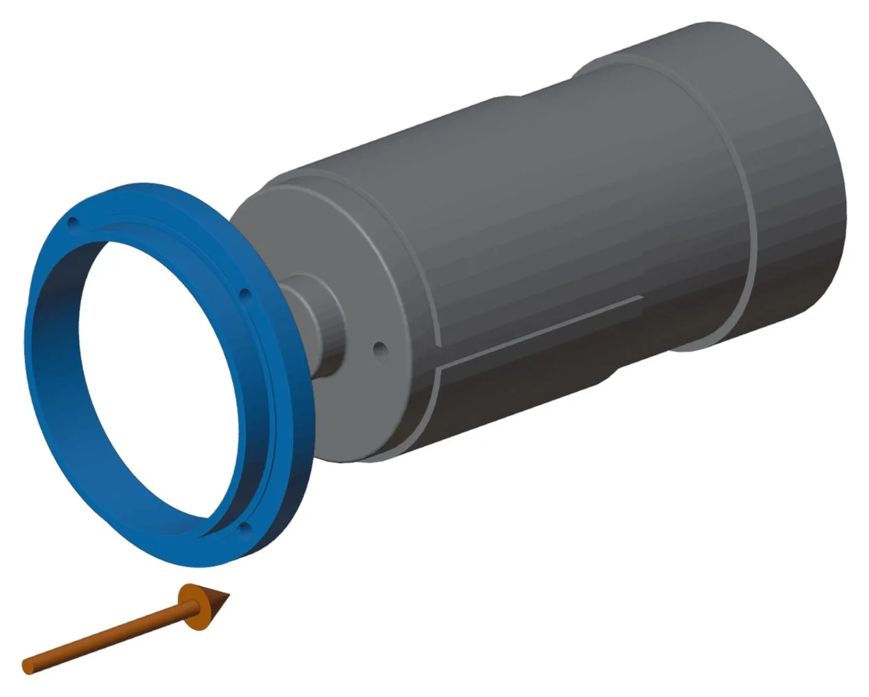
The back block goes on from the side with the motor pinion. Find the small notch on the motor's side, hook the back block on at an angle at the notch, then straighten it and push it on from the front. It's a snug fit.
Motor spacer (optional, not recommended): only use it if the module is mounted from the front face alone. Skip it if you have the Frame Kit or are mounting from both faces. We don't recommend it because it lowers efficiency by not letting the module float between your drivetrain plates. To fit it, twist off the motor's back cap, slide the spacer on, and put the cap back on.
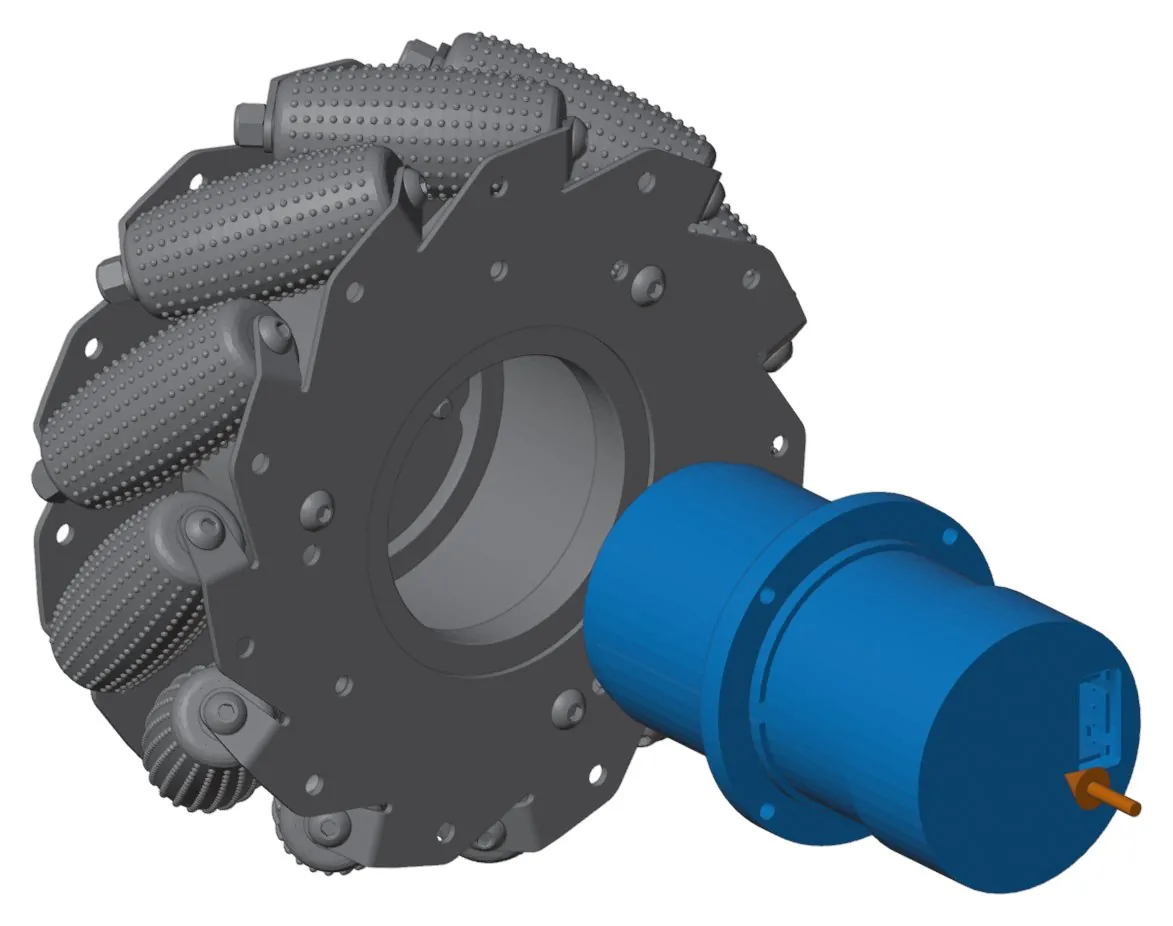
Keep a finger on the two motor screws. Slide the motor into the back of the wheel and push until the back block snaps into the back bearing. You may need to wiggle the motor a little to get it seated.
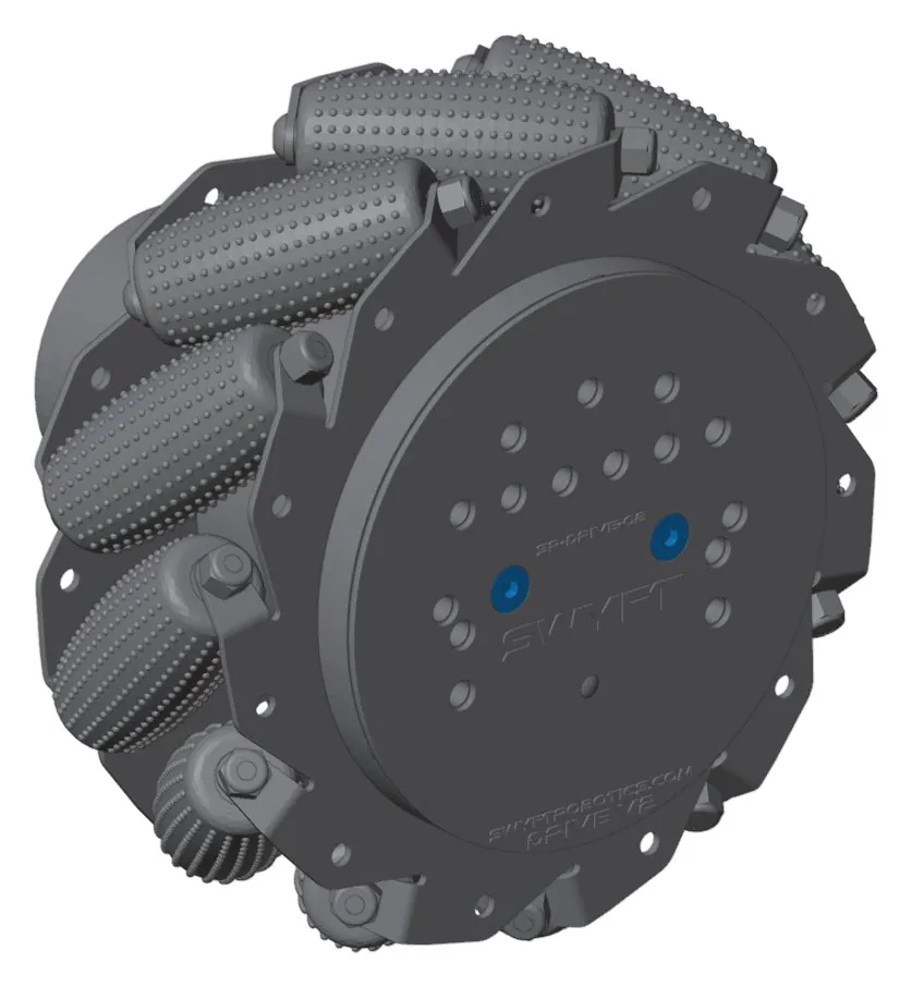
Press down on the two motor screws and turn the motor about 90° until you feel a click. That's the screws dropping into the motor's holes. Now tighten both.
If a screw keeps turning without tightening, it's in the wrong pair of holes. Back the screws out a little, turn the motor about 90°, and let them click into the right holes.
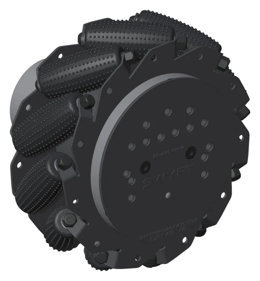
Turn the wheel by hand. You should feel a little resistance because it's turning the motor. That's normal. It gets smoother as it wears in. If you feel tight spots or ticking, the front block isn't fully seated. Go back to step 7.
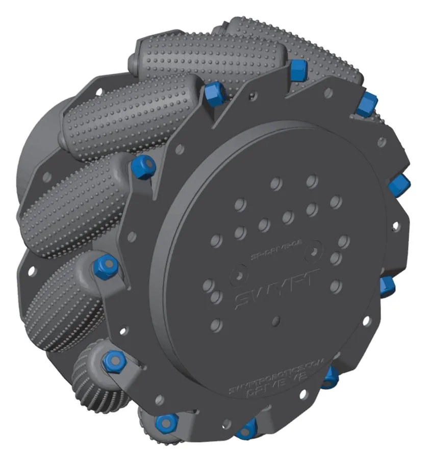
Hold each roller's lock nut with the 5.5 mm wrench and tighten the screw with the 2 mm Allen key until the roller no longer spins freely. Then back it off about one turn. The roller should spin freely and not slide along the screw. Lock nuts don't need Loctite. Do this for every roller.
Overtightening is the most common mistake. If a roller drags, loosen it a little more.
The module is done. Build the other three the same way.
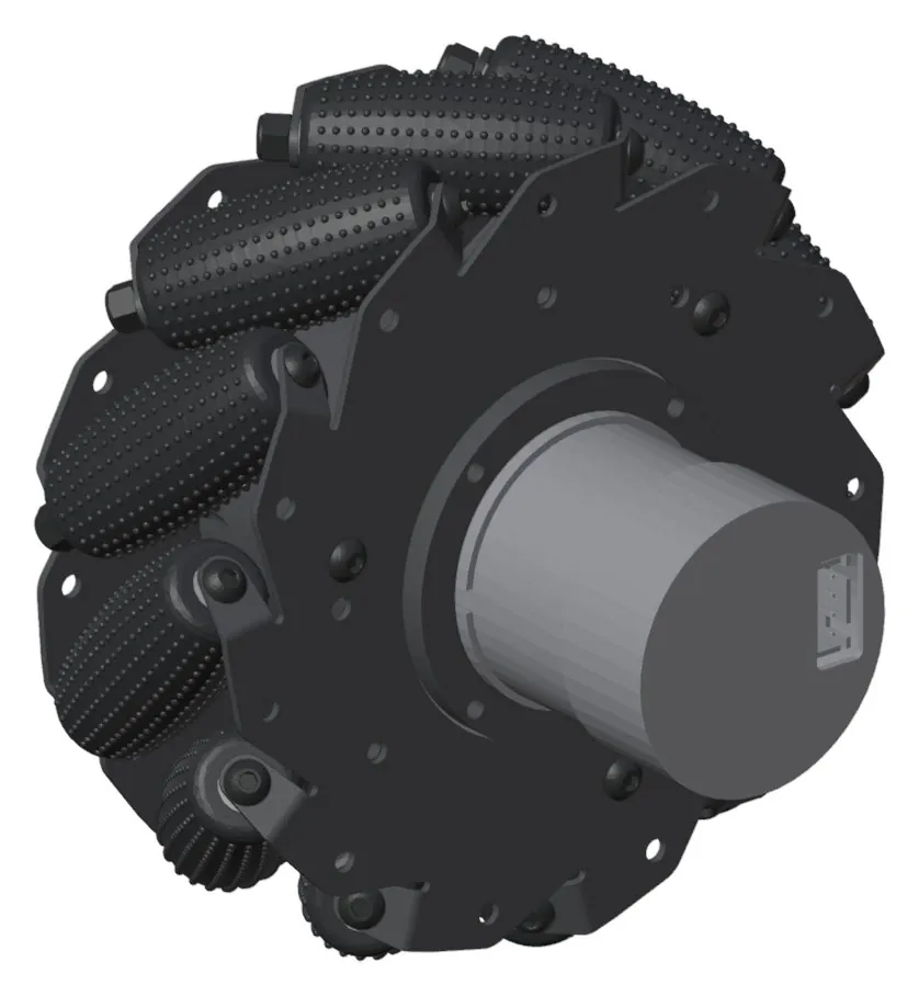
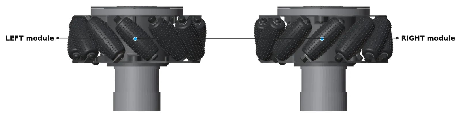
LEFT and RIGHT modules have their rollers angled in opposite directions. Put the two LEFT modules on one diagonal of the robot and the two RIGHT modules on the other diagonal. Like any mecanum drivetrain, the rollers form an X seen from above and an O seen from underneath.
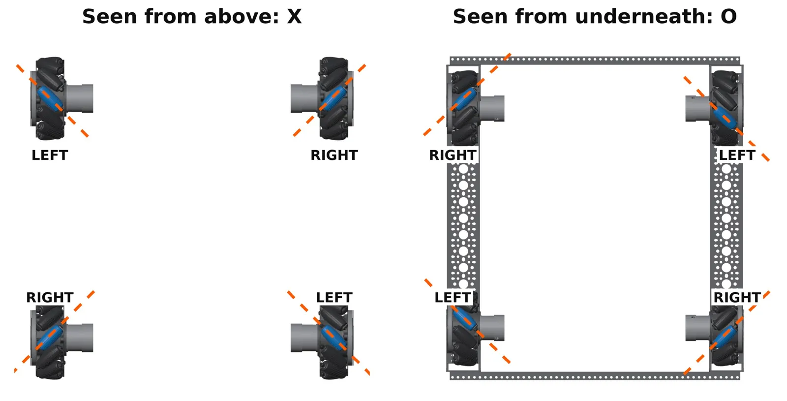
The Frame Kit lets you build a drivetrain without custom plates. Use the Onshape configurator linked on the product page to plan the channel layout before you start. The channels can be cut to any length. The 110 mm Frame Kit fits both 110 mm and 86 mm modules. The 86 mm Frame Kit fits 86 mm modules only.
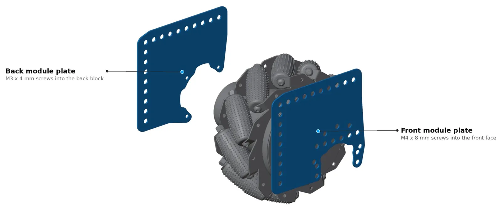
The two plates can turn separately for now. That's expected, and the channels lock them together.
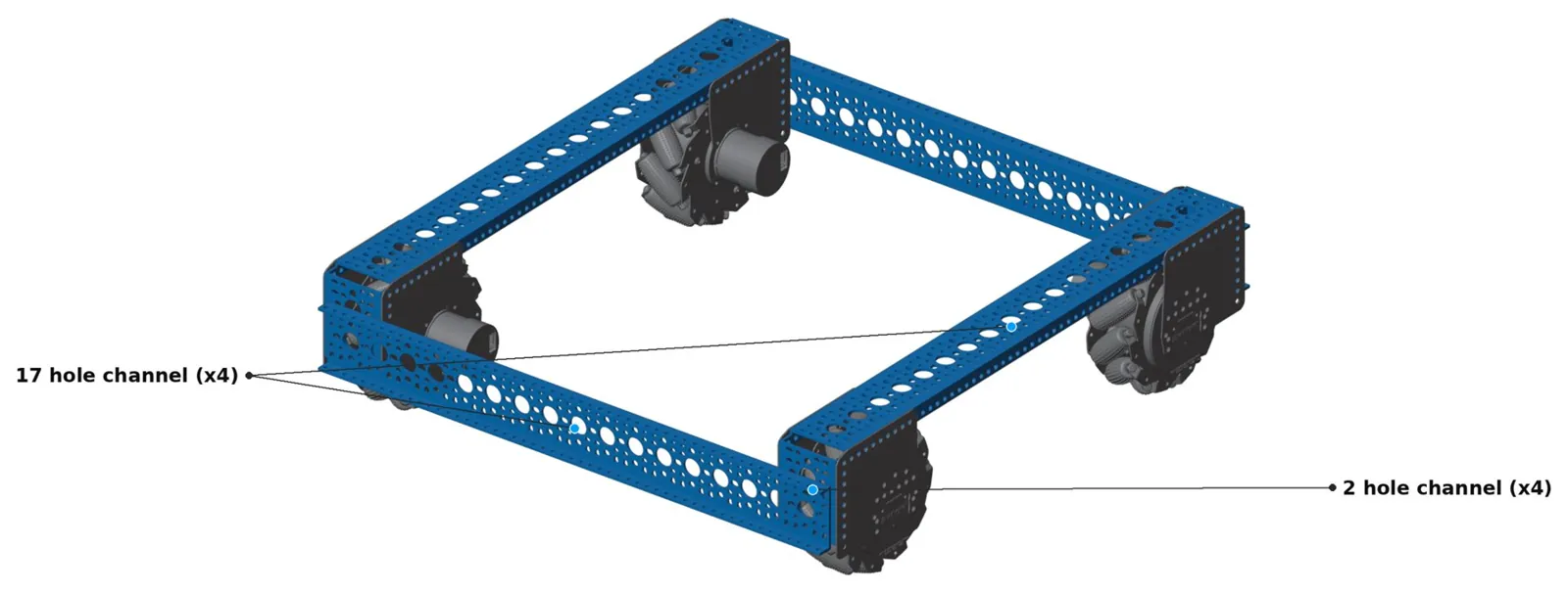
Bolt the channels between the module plates to match your layout.
Discord support server (fastest), website chat, or support@swyftrobotics.com.